EMI Shielding in Defense Cable Assemblies
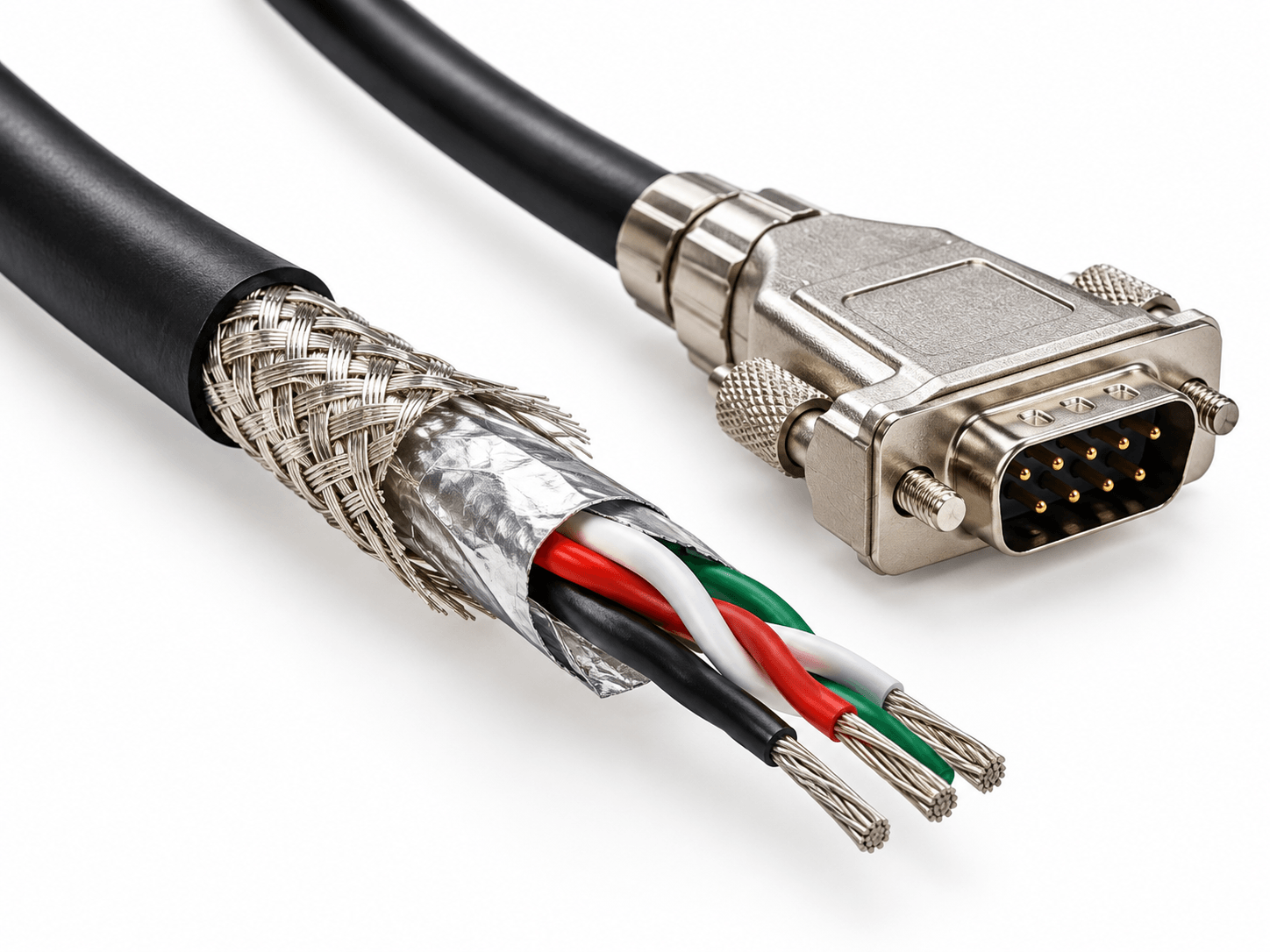
A cable assembly can pass a shield continuity test without demonstrating effective electromagnetic interference (EMI) protection. Shielding effectiveness also depends on termination geometry, transfer impedance, frequency, and installation conditions.
Continuity Versus Shielding Effectiveness
Continuity and resistance measurements can detect open connections or excessive resistance but don’t establish shielding effectiveness across the frequencies of interest.
A shield pigtail, for example, may provide electrical continuity while introducing inductance that compromises high-frequency performance.
Specifications should distinguish between continuity requirements and shielding-effectiveness requirements rather than treating them as interchangeable.
Shield Termination and Connector Interfaces
Termination geometry can significantly affect high-frequency shielding performance. Circumferential (360-degree) shield terminations generally offer lower high-frequency impedance than long pigtail connections, although requirements depend on the application.
Assembly documentation should define:
- Shield termination method and location.
- Connector and backshell interfaces.
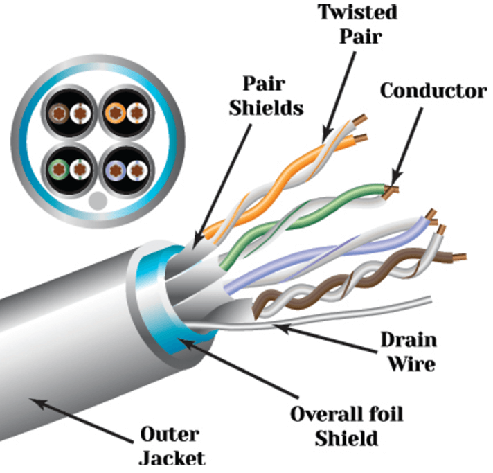
- Treatment of individual and overall shields.
- Shield continuity through transitions and breakouts.
These details should be specified rather than inferred from the cable’s shielding construction.
Assembly Performance Versus Installed Performance
A cable assembly’s shielding characteristics don’t necessarily predict system-level electromagnetic compatibility (EMC).
Enclosure interfaces, chassis connections, grounding architecture, and installation geometry can affect electromagnetic coupling.
Assembly-level verification and system-level EMC testing therefore serve different purposes. Meeting cable assembly acceptance criteria does not establish that the installed equipment meets its EMC requirements.
Defining Acceptance Criteria
For build-to-print assemblies, specifications should identify the required verification methods and limits. Depending on the application, these may include:
- Shield continuity or resistance limits.
- Termination workmanship and inspection criteria.
- Shielding-effectiveness or transfer-impedance measurements.
- Applicable test methods, frequency ranges, and acceptance limits.
- Required inspection and test documentation.
Verification requirements should reflect the assembly’s design and contractual specifications.
Custom Shielded Cable Assemblies at TMC
TMC–The Mate Company manufactures custom cable assemblies and wire harnesses for military and aerospace applications, including external shielded cable assemblies.
Explore TMC’s military and aerospace manufacturing capabilities.
Need custom cable assemblies manufactured to defined shielding requirements? Request a quote from TMC with your drawings, specifications, quantities, and applicable acceptance criteria.