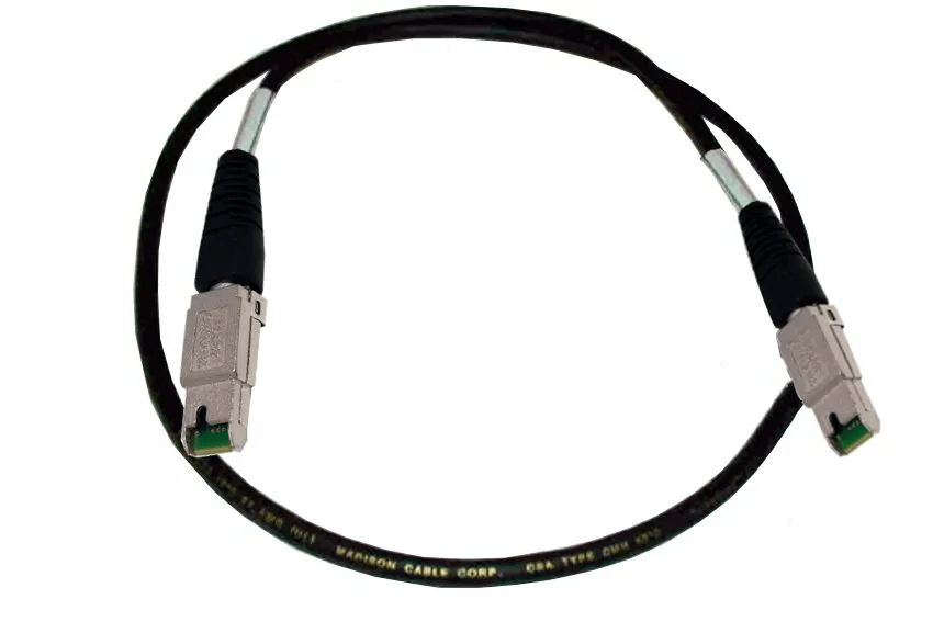
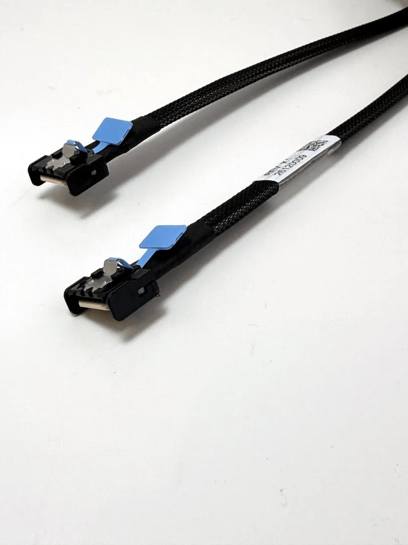
MCIO 4i Connectivity For PCIe Gen4 And Gen5
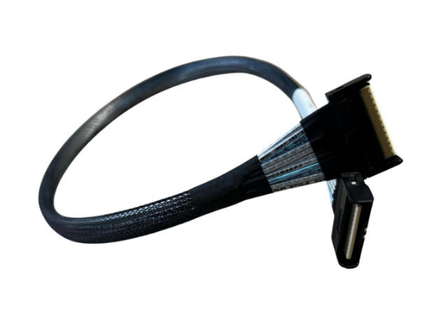
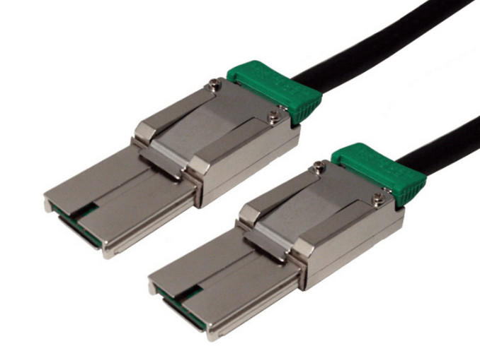
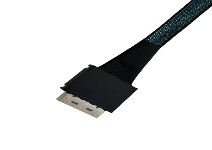
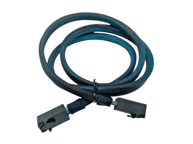
MCIO 4i cables provide compact internal connectivity for PCIe Gen4 and PCIe Gen5 links in servers, NVMe storage platforms, and high density computing systems. The interface carries four high speed lanes through a small connector footprint, allowing designers to route bandwidth intensive links where PCB area and chassis space are limited. Depending on the assembly design, MCIO 4i cabling may also incorporate sideband conductors or specialized channel mappings for specific hardware architectures.
Understanding The MCIO 4i Interface
MCIO, commonly known as Mini Cool Edge IO, is an internal interconnect format developed for dense, high speed system layouts. The 4i configuration provides four primary high speed lanes that can be routed between compatible host boards, backplanes, adapters, controllers, and endpoint devices.
The compact connector format is particularly useful in modern servers where processors, accelerators, NVMe devices, memory modules, riser cards, and cooling hardware compete for limited board and chassis space. A smaller interface can simplify internal routing while allowing system designers to maintain high lane density.
MCIO 4i should be evaluated as part of the complete platform architecture. Matching connector shapes do not guarantee functional compatibility. Lane assignment, signal direction, pin mapping, sideband requirements, host capabilities, and endpoint behavior must all correspond with the intended system design.
MCIO 4i Operation In PCIe Gen4 Platforms
PCIe Gen4 operates at 16 GT/s per lane, doubling the signaling rate of PCIe Gen3. When four lanes are configured as a PCIe x4 link, the interface can provide substantial aggregate bandwidth for NVMe storage, internal expansion, and other data intensive applications.
An MCIO 4i cable can carry these lanes between compatible components within the chassis. Common connection paths may include motherboard to backplane links, controller to storage interfaces, and internal connections between PCIe capable subsystems.
At Gen4 signaling rates, the electrical channel must be managed carefully. Cable attenuation, connector transitions, impedance variation, PCB trace length, and crosstalk can affect available signal margin. Reliable operation therefore depends on the complete path rather than the cable assembly alone.
MCIO 4i Requirements For PCIe Gen5 Links
PCIe Gen5 increases the signaling rate to 32 GT/s per lane. This higher rate places tighter constraints on insertion loss, return loss, jitter, skew, and discontinuities throughout the channel.
For an MCIO 4i link, the complete signal path may include transmitter package connections, motherboard traces, board connectors, cable conductors, receiving connectors, endpoint traces, and additional transitions. Each segment contributes to the total channel behavior.
Cable length becomes increasingly important at Gen5 rates because attenuation rises with frequency. A shorter assembly may provide greater signal margin, but supported distance cannot be determined from connector type alone. Cable construction, conductor geometry, PCB design, equalization behavior, and the platform channel budget all influence the final result.
For this reason, a PCIe Gen5 deployment should use an MCIO assembly specifically designed and validated for the intended signaling environment.
Four Lane Architecture And Channel Mapping
The 4i designation identifies an internal four lane configuration. In a typical PCIe implementation, these lanes can support an x4 link when the host and endpoint are configured for the same width.
Each PCIe lane contains differential transmit and receive paths. Maintaining controlled impedance and consistent pair geometry is necessary because variations can introduce reflections, skew, and other impairments at high signaling rates.
Channel mapping must also match the system design. Two MCIO 4i cables may use similar connectors while differing internally in pin assignment or auxiliary conductor use. Engineers should therefore verify the wiring configuration rather than relying only on connector appearance.
Sideband Signals And Alternative Configurations
Some MCIO 4i assemblies include conductors for sideband functions. Depending on the platform, these signals may support management, reset, clock related functions, presence detection, control, or other hardware specific requirements.
Other cable configurations may allocate available conductors differently. For example, certain assemblies can use conductors normally assigned to sideband functions to provide additional channel paths. In such cases, sideband support may no longer be available.
This distinction is important when selecting cables for server and storage hardware. A six channel configuration should not automatically replace a four channel assembly with sidebands, even when the external connectors appear similar. The host and endpoint pinouts must match the exact cable architecture.
Signal Integrity Across Gen4 And Gen5 Channels
Signal integrity is a central consideration in MCIO 4i deployments. High speed differential links can be affected by insertion loss, return loss, crosstalk, pair skew, impedance discontinuities, and connector transition quality.
PCIe Gen5 links are particularly sensitive because the higher signaling rate reduces available electrical margin. Excessive cable length or poorly controlled transitions can contribute to unstable link training, reduced negotiated speeds, or increased error activity.
Cable routing can also influence channel behavior. Tight bends, compression, twisting, and repeated mechanical stress may alter conductor geometry. Assemblies should be routed according to their mechanical specifications and protected from pressure created by chassis panels, heat sinks, drive cages, or other internal structures.
Compatibility Beyond Connector Matching
MCIO 4i compatibility involves several electrical and architectural factors. Before deployment, engineers should confirm:
- Lane Count And Link Width
- Transmit And Receive Mapping
- Connector Pin Assignment
- Sideband Signal Requirements
- PCIe Generation Support
- Host Controller Capabilities
- Endpoint Compatibility
- Firmware And Platform Requirements
A PCIe Gen5 capable cable cannot upgrade a Gen4 host or endpoint to Gen5 operation. Every active and passive component in the path must support the intended generation.
Similarly, a cable designed for one server platform may not function in another system if the lane mapping or auxiliary signals differ. Detailed hardware documentation should be reviewed before substitution.
MCIO 4i In NVMe Storage Architectures
NVMe storage is a major application area for compact PCIe cabling. High density servers may contain multiple NVMe devices connected through backplanes, adapters, or internal routing assemblies.
MCIO 4i cables can provide a compact method for carrying PCIe lanes between a host platform and compatible storage hardware. Their small connector footprint can be useful where multiple links must be positioned near processors, PCIe switches, drive backplanes, or other densely arranged components.
Actual NVMe support depends on the complete platform. The cable itself does not provide protocol conversion, lane bifurcation, or device management. These functions must be supported by the host architecture and associated hardware.
Mechanical Routing And Thermal Management
Internal cable routing must account for both mechanical protection and cooling requirements. Dense server chassis often contain fan modules, processor heat sinks, accelerator cards, power distribution components, and storage cages.
MCIO 4i cables should be routed without sharp bends or excessive tension. Connector strain should be minimized, particularly near board mounted receptacles. Cables should not be trapped beneath chassis covers or compressed against components.
Airflow is equally important. Poor cable placement can obstruct cooling paths and increase local temperatures around processors, NVMe drives, voltage regulators, and expansion hardware. Organized routing can help maintain both accessibility and thermal performance.
Common Applications
- PCIe Gen4 And PCIe Gen5 Internal Interconnects
- NVMe Drive Backplanes
- Enterprise Server Platforms
- High Density Storage Appliances
- Motherboard To Backplane Links
- Internal Controller Connections
- PCIe Expansion Architectures
- Compact Computing Systems
Best Practices For Deployment
Confirm the complete pinout and lane mapping before installing an MCIO 4i cable. Pay particular attention to differences between assemblies with sideband conductors and versions using alternative channel configurations.
Use the shortest practical cable length that satisfies the chassis layout and validated system design. Avoid unnecessary loops, sharp bends, and excessive mechanical force. Maintain adequate separation from components that can create heat or physical pressure.
For PCIe Gen5 links, validate operation under realistic system conditions. Check negotiated link width and speed, review error behavior, and confirm stability across expected thermal and workload ranges. Firmware and BIOS settings should also be reviewed where link configuration depends on platform controls.
FAQ (Frequently Asked Questions)
1. What Is The Primary Function Of An MCIO 4i Cable?
An MCIO 4i cable carries four high speed internal lanes between compatible components in PCIe, NVMe, server, and storage architectures.
2. Can The Same MCIO 4i Cable Be Used For PCIe Gen4 And Gen5?
Only when the specific assembly and complete channel are designed and validated for the intended PCIe generation.
3. Why Do Some MCIO 4i Cables Include Sideband Conductors?
Sideband conductors can carry management, control, reset, detection, or other platform specific signals required by compatible hardware.
4. Can Two MCIO 4i Cables With Identical Connectors Have Different Functions?
Yes. Internal pin mapping, lane assignment, sideband support, and signal direction can differ between cable configurations.