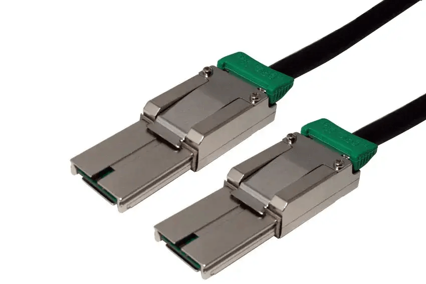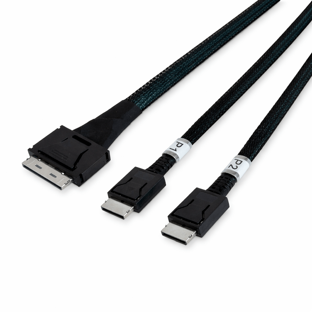
Internal PCIe Connectivity with OCulink 8x to Dual 4x Breakout Cables
OCulink 8x to dual 4x cables provide a method for distributing a single PCIe x8 interface into two separate x4 links. This configuration is used in systems that require multiple high-speed device connections from a limited number of PCIe ports. By leveraging lane bifurcation at the platform level, these cables support efficient bandwidth allocation across storage and expansion devices.
Lane Segmentation and Interface Structure
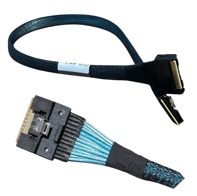
The OCulink 8x interface, defined under the SFF-8611 specification, carries eight PCIe lanes through a compact internal connector. In a breakout cable design, these lanes are divided into two independent x4 channels, each routed to its own endpoint connector.
This segmentation allows a single host connection to support two devices simultaneously. Each x4 link operates independently, enabling parallel communication without shared bandwidth contention beyond the original x8 allocation.
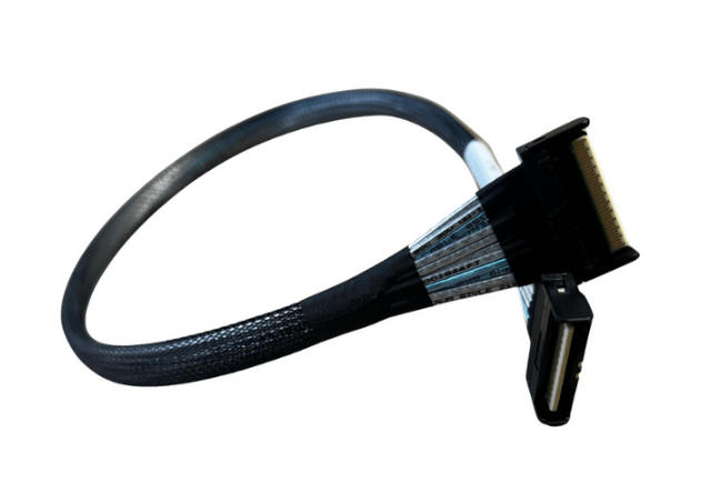
The cable functions as a passive interconnect, preserving direct electrical pathways between the host and connected devices.
PCIe Signaling and Electrical Characteristics
High-speed PCIe signaling requires strict control over electrical properties such as impedance, insertion loss, and crosstalk. OCulink breakout cables are constructed with matched conductors and shielding to maintain signal integrity across all lanes.
Splitting the cable into dual branches introduces additional routing considerations. Both branches must maintain consistent electrical behavior to ensure stable link training and sustained throughput. Mechanical stress, sharp bends, or uneven cable paths can impact signal quality, particularly at higher PCIe generations.
Careful cable placement and adherence to physical handling guidelines are necessary to maintain reliable operation.
Platform Compatibility and Configuration
Deployment of OCulink 8x to dual 4x cables depends on system support for PCIe bifurcation. The host platform, typically configured through BIOS or firmware settings, must be capable of dividing an x8 slot into two x4 links.
These cables are used in systems equipped with OCulink ports for internal connectivity. Typical endpoints include NVMe storage devices, PCIe expansion modules, and specialized accelerators.
Compatibility also requires correct alignment of connector types and validation of firmware support for multi-device configurations.
Typical Deployment Scenarios
- Multi-drive NVMe configurations in servers
- PCIe expansion in space-constrained systems
- High-density storage and compute nodes
- Hardware validation and testing platforms
- Modular infrastructure designs
Implementation and Routing Considerations
Effective internal layout is important for both performance and thermal management. Cables should be routed to minimize obstruction of airflow and avoid proximity to heat-intensive components.
Appropriate cable length selection helps prevent mechanical strain and reduces excess slack. Connectors should be securely installed to maintain consistent electrical contact.
System designers should also evaluate overall power and thermal conditions when connecting multiple PCIe devices through a single interface.
FAQ (Frequently Asked Questions)
1. Is PCIe bifurcation handled by the cable itself?
No, bifurcation is controlled by the host system and must be enabled in firmware or BIOS.
2. Can both x4 links be used at the same time?
Yes, when properly configured, both connections operate independently and simultaneously.
3. Which PCIe generations are supported?
Support varies by cable design and system, commonly including PCIe Gen4 and Gen5.
4. Are there recommended cable length limits?
Yes, shorter cable lengths are preferred to maintain signal integrity at higher data rates.