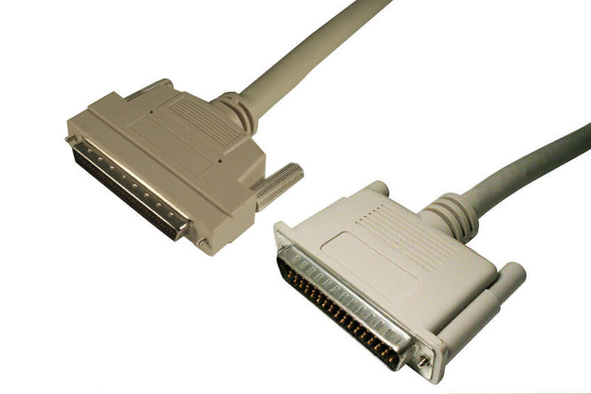
Installation Guidelines for HD68 Internal SCSI Terminators in Legacy Systems
HD68 internal SCSI terminators are used to electrically terminate 68 pin parallel SCSI buses inside servers, storage arrays, and industrial systems. These terminators are designed for internal ribbon cable interfaces and are required to maintain signal integrity across Ultra320, Ultra160, Ultra2, and earlier single ended or LVD configurations. Proper installation ensures stable communication and prevents reflection related errors in legacy enterprise hardware.
Understanding the Role of SCSI Termination
Parallel SCSI operates as a multi drop bus architecture. Electrical signals travel along the ribbon cable and must be terminated at both physical ends of the bus. If the bus is left unterminated or improperly terminated, signal reflections occur. These reflections can introduce timing errors, data corruption, or intermittent device detection failures.
An HD68 internal terminator provides controlled impedance matching at the end of the bus. This matching minimizes reflections and stabilizes voltage transitions across the data and control lines.
SCSI Mode Compatibility and Signaling Behavior
Before installation, verify the signaling mode used by the SCSI controller and attached devices.
Single Ended and LVD Environments
Legacy systems may operate in single ended mode or low voltage differential mode. Some HD68 internal terminators support automatic mode detection, adjusting termination characteristics based on bus signaling. Others are fixed mode and must match the bus type exactly.
Using an incompatible terminator can force the bus into single ended fallback mode or prevent reliable negotiation at higher transfer rates.
Ultra2, Ultra160, and Ultra320 Considerations
Higher speed parallel SCSI standards increase sensitivity to impedance mismatch and stub length. Ultra160 and Ultra320 environments require active termination with voltage regulation to maintain stable signaling. Passive terminators are not suitable for these high speed implementations.
Physical Placement and Bus Topology
Termination must be applied at both physical ends of the SCSI cable, not simply the last device in logical order. Internal ribbon cables often include multiple device connectors, with the final connector at the end of the cable designated for termination.
Installers should verify:
-
The controller location on the cable
-
The position of all connected devices
-
The actual physical end of the ribbon cable
-
Whether onboard termination is enabled on the controller or device
Incorrect placement can leave one end of the bus unterminated, even if a terminator is present elsewhere.
Mechanical and Space Constraints
Legacy server chassis and storage enclosures often have limited clearance behind drive bays or backplanes. Low profile HD68 terminators are designed to fit within tight ribbon routing paths without obstructing airflow or interfering with adjacent components.
Pass through designs may be required when the final ribbon connector must remain available for cable routing purposes. Confirm that the selected terminator does not create excessive cable bend radius or contact with other hardware.
Termination Power Requirements
Most internal SCSI terminators draw termination power from the TERMPWR line supplied by the host adapter or devices on the bus. Installers should confirm that termination power is enabled and stable. Some enterprise controllers allow termination power to be enabled or disabled through firmware or hardware jumpers.
Unstable or absent termination power can cause inconsistent bus behavior that may appear as intermittent device failures.
Common Deployment Environments
HD68 internal SCSI terminators are typically found in:
-
Rack mount servers using parallel SCSI backplanes
-
RAID subsystems with Ultra160 or Ultra320 controllers
-
Industrial control systems with extended lifecycle requirements
-
Legacy storage enclosures with fixed ribbon cable assemblies
These environments often rely on proper termination to maintain operational continuity.
Best Practices before Installation
Prior to installing an HD68 internal SCSI terminator:
-
Confirm the SCSI signaling mode in use
-
Ensure the terminator supports the required speed and voltage level
-
Identify the true physical end of the bus
-
Verify termination power availability
-
Check physical clearance and airflow impact
Accurate labeling and documentation of termination points can simplify future maintenance in mixed generation environments.
FAQ (Frequently Asked Questions)
1. What happens if a SCSI bus is not properly terminated?
Signal reflections may occur, leading to data corruption, intermittent detection issues, or complete communication failure.
2. Can an HD68 internal terminator support multiple SCSI standards?
Many active terminators support Ultra2, Ultra160, and Ultra320 standards, provided they are designed for LVD operation.
3. Should onboard termination be disabled when using an external terminator?
Yes, termination should exist only at the two physical ends of the bus. Redundant termination can degrade signal integrity.
4. Are passive terminators suitable for Ultra320 environments?
No, Ultra320 requires active regulation to maintain proper impedance and voltage stability.